


 Description

Our modules are ideal for any application that uses the photoelectric effect as a clean energy source because of its minimal chemical pollution and no noise pollution. Thanks to its design, can be integrated easily into any installation.
These PV modules use high-efficiency silicon cells to transform the energy of sunlight into electric energy. Each cell is electrically rated to optimize the behavior of the module.
Our modules comply with all safety requirements only flexibility but also double insulation and high resistance to UV rays, for all that are suitable for use in outdoor applications.
The photovoltaic modules from Solar Innova have passed several international certification requirements and continue to even improve on an already superior quality and performance of products of proven technologies. Quality is one of our core principles and the pursuit of quality is the engine of the company's future, in our desire to continually offer better products.
 Quality

Controls during the manufacturing process
During the manufacturing process of the materials are controlled under only some critical parameters in the marketplace. With these controls Solar Innova makes the best modules providing long life and high reliability of operation.

Generally, the process parameters such as gel content, adhesions and hotspots are constantly checking by the department of Process Engineering Solar Innova, assuring that these critical controls provide the highest quality at each point in the manufacturing process of the product.
1.- Gel Content Test
 Gel Content Test (Control Test of EVA) is a process that is performed to carry out checks on the most critical phase of the construction of a photovoltaic panel: the lamination; for a better guarantee of lifetime of the module.
It is done by periodically sampling, analyzing all the data correlating weekly rolling with, guidelines Entry Inspection EVA material internal management in production and periodic tests in a climatic chamber. In Solar Innova use the latest techniques of analysis, which allows working shoklet distillation with xylene always clean. DSC analysis in addition to the gel content of EVA allows us to see the kinetics of radiation and characterize the additives that embody.
2.- Hot Spot Test
Continuous monitoring is done by: test samples collected directly from the manufacturing lines, whether cells, strips or even complete modules.
All lines are subject to the test weekly. All lots are tested in facilitating inspection guidelines classification and approval of suppliers.
3.- Power Test Cells
Are conducted through incoming inspection guidelines, constant sample test online, and CTM permanent control for continuous power and homogeneous modules.
(CTM: Cell To Module, this parameter indicates cell Watts lost inevitably to make a panel. If this efficiency is good and steady, guarantees being manufactured correctly).
4.- Peel Test
Through control laminates are done reviewing the internal bond all the layers that make up the module and products are inspected weekly all production lines, ensuring against future delaminations module.
 Test
Test

Once the assembly has proceeded modules are subjected to the following tests:
Measurement of V-I Characteristics
During the analysis performed following measurements:
Pmpp (W) = Maximum power.
Vmpp (V) = Voltage at maximum power.
Impp (A)= Current at maximum power.
Voc (V) = Open circuit voltage.
Isc (A) = Short circuit current.
FFm (%) = Form Factor.
n (%) = Performance.
RsH (Ω) = Parallel resistance.
Rs (Ω) = Series resistance.
The electrical characteristics of current and working voltage, measured for each module, will define the amperage which will work for this installation and sections of conductors and other electrical components (cables, diodes, wiring, etc.).
Data records are measured in real time. The data is transferred to a computer, where the values are processed using the software.

Once the measurement modules are labeled on the rear part with a barcode containing a serial number traceable to the date of manufacture for identification.
![]()
ELCD Test = Electroluminescence Crack Detection Test
The electrical circuits of all Solar Innova modules are evaluated with an EL test machine.
Physics
Electroluminescence is the result of radiative recombination of electrons and holes in a material. The excited electrons release their energy as photons – light. This light can be captured as an electroluminescence image, resulting in a picture which allows evaluation.
Practical application
An EL test machine consists of a black room in which the solar module is placed, a DC power supply, two cooled CCD camera’s. With the power supply, current will be sent through the solar module. All electrical active zones will start to emit infrared light. This infrared light will be acquired by the camera’s. This allows us to visualize all electrical active and non active areas of the solar module.
Evaluation
This test allows the detection and visibility of material defects in the manufacture of photovoltaic cells. As a result, it is possible to evaluate the quality of the manufacturing process of the cells and any other defect that may be caused by the subsequent handling of the photovoltaic panels. This method may locate the points where the series resistance is abnormally high, cracks in cells and areas where there is no electrical connection. These issues directly impact the longevity of the module and hence their profitability because if not, the module itself runs the risk of having to be replaced before amortization. In particular, the microcracks have a significant effect on long-term stability of performance parameters of photovoltaic panels. The test can detect hidden defects unobtainable by other test methods (flash test, features V-A, or thermal camera).

The basis of this test is an inspection of the internal structure of the panel, which is invisible to the naked eye. These images are some examples:

Advantages
Detection of microcracks in broken cells and cellular structures.
Detection of defects in contact bars.
Detection of failure or interruption printed with fingers.
Detection of inhomogeneity and foreign matter in the crystalline silicon.


Insulation Test
We check that the modules do not have dielectric and insulation resistance value according to section 10.3 of IEC/EN Standard 61215 ruptures.
We check that the modules provide an insulation resistance under wet conditions according to section 10.15 per IEC/EN 61215 Standard.
Each module sequentially undergoes during the manufacturing process to the following tests:
Effectiveness of ground continuity.
Dielectric strength.
Insulation resistance.
Power.
Consumption.
Leakage currents.

Flash Test
The basic test of the performance parameters of a test flash. This process is intended to acquire the electrical characteristics of the fabricated module for further sorting in power ranges which will serve for a good rating to reduce mismatching. The electrical measurement module is a class A solar simulator according to final wiring configuration, and under standard test conditions (STC):
Irradiance: 1,000 W/m2
Spectral distribution: 1,5 A.M. (Air Mass)
Incidence: normal
Temperature: 25º C
Under such conditions are measured, the maximum power that can deliver the module, Pmax, the short-circuit current, Isc, the open circuit voltage, Voc and the form factor. The electrical characteristics of current and working voltage, measured for each module, will define the amperage which will work for this installation and sections of conductors and other electrical components (cables, diodes, wiring, etc.).
Once the measurement modules are labeled on the back with a sticker clearly visible and indelible which reflects the logo of the manufacturer, model and technical data of each module.

Once the measurement modules are labeled on the back with a sticker clearly visible and indelible which reflects the manufacturer's logo, model and technical data of each module.

Flash Test results are delivered to the customer in electronic file format spreadsheet (.xls) with the following characteristics of each of the photovoltaic modules:
Serial number.
Barcode.
Pmpp (W) = Maximum power.
Vmpp (V) = Voltage at maximum power.
Impp (A)= Current at maximum power.
Voc (V) = Open circuit voltage.
Isc (A) = Short circuit current.
FF (%) = Form Factor.

Climatic Test Chamber
Solar Innova use climatic chamber for conducting durability tests as specified in the IEC/EN 61730 standard, in this way ensures that our modules can withstand during its lifetime the various environmental conditions that reflect the specifications of the IEC/EN and UL.
This type of testing is done with cameras laboratory tests, of which the most common are the climatic chambers for environmental testing and accelerated solar simulation, which allow faithfully reproduce, at laboratory scale, the different climates they can suffer PV modules exposed to the weather.
Functions such as corrosion, rain, ice, snow, hail, dust and sand, air pollution, moisture, cold and heat, thermal shock and intense radiation, can be accelerated to extrapolate values to the expected lifetime of use and investigate new more effective and durable products.
Climatic test we perform are:
UV preconditioning: bandwidth 280 nm to 385 nm
Maximum intensity of solar irradiation: 250 W/m²
Module temperature: +60 ±5° C
UV irradiation total of 15 kW/m² and a minimum of 5 kW/m² in bandwidth between 280 nm and 320 nm
Thermal cycles: 50 (b) or 200 (a) cycles from -40 °C to +85 °C
Freezing and humidity: 10 cycles from -40° C to +85° C and 85% RH
Most heat: 1,000 h at +85° C and 85% RH

Salt Fog Chamber Test
Solar Innova has a chamber for exposure to corrosion for large samples as specified in the IEC/EN 61701 standard, which we test with salt spray and humidity, or basic cycles, for large sample sizes and assembled components.
The test offers an advantage assembled components to evaluate the combination of potentially incompatible materials. Our cabin allows testing with large samples and fully assembled components.
Installing lamps MH (metal halogen) or MHG (global metal halogen) in the chambers passable enhances testing capabilities. It is now possible to test the resistance to UV rays, corrosion and other environmental conditions and entire sets of large samples in the same unit.

Thermographic Camera Test
The temperature of any surface can be obtained using a thermographic camera.
The thermal imaging camera measures the temperature of the surface of the photovoltaic panels in charge and often reveal the presence of trouble.

With the imager can detect faults in electrical components such as bypass diodes and junction boxes and mechanical defects such as delamination or cell damage. Thermography also helps locate problems with welds, which eventually can cause long-term problems.
Thermal imagers output are images that determine the range of temperatures on the surface of the measured object. Basically, the camera becomes invisible infrared radiation at wavelengths of visible light. Each color defines a certain temperature.
Thermography provides a quick and simple information about solar module and determines the quality and reveals the existence of possible future risks.


Sand and Dust Test
Test simulates the typical erosion effect of heavy desert sandstorm situation. This endurance testing is critical to determine the reliability and longevity of solar PV panels in real world conditions along their lifetime.
The considerable increase in the number of PV installations in desert regions makes it essential to develop solar modules that can withstand the strong impact of high-velocity sand and avoid the accumulation of dust on the surface of the modules.

 Installation

Carefully read the following product documentation and safety instructions.
Failure to follow these instructions will make the module warranty void.
 Guarantee

All solar panels manufactured by Solar Innova have the following minimum guarantees:
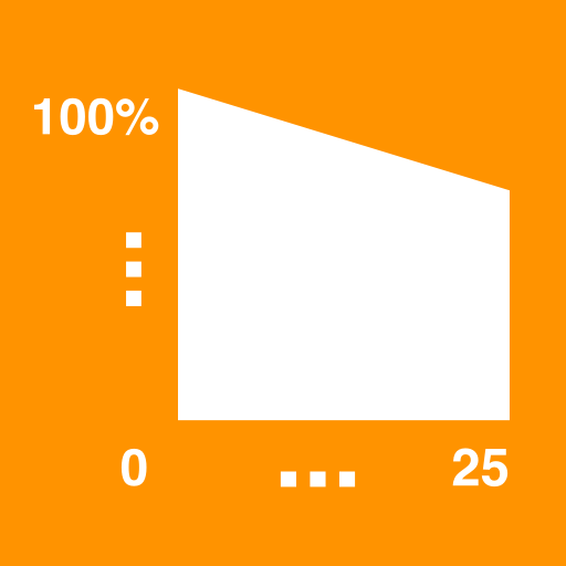
Linear Performance Guarantee
The linear power guarantee Solar Innova modules ensures a higher power than that of the other photovoltaic module during the lifetime of the plant. The combination of our high quality modules with an optimal plant design results in maximum performance for end users and allows you the maximum performance guarantees to their customers without having to worry.
Linear performance warranty Solar Innova
Standard performance warranty

Importance of Ensuring Adequate Power
Solar Innova offers great advantages with its linear power warranty. Other power guarantees are reduced in stages over the time periods established. These guarantees remain staggered continuous from beginning to end in the same period. Considering the drastic reduction in the coverage of the guarantee to pass a temporary step to another, there is the possibility that the module power drops sharply at the beginning of the period, without being able to claim the manufacturer. To prevent unexpected power loss out of warranty, it is best to have a potency guarantee is reduced linearly over the lifetime of the module.
 Advantage
Solar Innova Quality

Solar Innova products are made with the highest quality components and the latest technology, thanks to the excellent factory equipment and control of the entire manufacturing process. In addition, our products offer excellent design and finishes.
Solar Innova has a wide range of photovoltaic solar panels that cover all market needs both feeding operation as isolated facilities. Besides offering the panels that we develop, manufacture and market, we advise our clients in everything that you may require, through our engineering department.

High Standards

Solar Innova has obtained in its factory a multitude of distinctive quality independent standardization bodies and control, demonstrating continued compliance with high standards of safety and quality in their products.
Outstanding quality, reliability above average and superior performance distinguish the Innova Solar modules. For this to continue to keep well, the modules are regularly a series of thorough tests and trials not only in the R & D and factory quality, but also through independent certification institutes.
In Solar Innova, production efficiency and supreme quality contribute decisively to the high degree of international competitiveness.
Certificates ISO & OHSAS


The effectiveness and excellence in all our manufacturing processes are the main guarantee that ensures the highest quality Solar Innova modules.
Our factory (certified according to ISO 9001:2008, ISO 14001:2004 and BS OHSAS 18001:2007) meets stringent quality requirements that our organization has set: full supervision in each individual phase of the production process.
Certificates CE

The CE or European Conformity is a European brand for certain groups of services or industrial products. It relies on the directive 93/68/EEC. It was established by the European Community and the testimony by the manufacturer that the product meets the minimum legal requirements and technical security of the Member States of the European Union.
Certificates IEC/EN

All our panels are manufactured under strict quality control and classification. Certificates IEC/EN 61215, IEC/EN 61730, IEC/EN 61701, IEC/EN 62716 and characterization reports made in testing laboratories based on these standards, certify that all of our panels successfully pass the tests that have been and are suitable for use in any type of installation.
Certificates UL

Standard UL 1703 refers photovoltaic panels that meet the National Electrical Code (NEC) and the National Fire Prevention Association (NFPA) in the United States of America. The American National Standards Institute ANSI/UL 1703 covers North American requirements for the design and testing of PV modules on the rating of the safe electrical and mechanical operation throughout their expected lifetime. The tests also demonstrate that the efficiency of the panels is tested and confirmed to reach 90 % or more of the power indicated by the manufacturer.
Direct from the Manufacturer

Producing high-quality PV modules requires much precision in selecting all the materials individually. Our commitment to precision goes beyond manufacturing right through to delivering the products to our customers. We offer all the knowledge about our products to distributors, technicians and installers, with which we have close cooperation for long-term sustainable growth. All of our products are manufactured on our own production facilities and are subject to the highest quality standards. In our own laboratory we test modules to ensure compliance with all international standards and to ensure stable quality and performance of our products.
Controlled Goods Flow

The strictest quality management is applied throughout the complete production sequence to a visual, micro-optical, mechanical, and electrical final inspection continuously insuring the premium quality of photovoltaic panels.
We monitor the production process and flow of each module and ensuring the high quality of our modules.
Each module is identified by a bar code with a greater quality control and traceability is achieved.
Aluminum Frame 6063-T5

Our modules are completed with compact self-supporting frames made of aluminum alloy profiles T5 anodized treatment to achieve an optimal moment of inertia weight and to obtain greater rigidity and resistance to twisting and bending.
The number corresponds to the 6063 U.S. standard extruded aluminum, while the T5 indicative refers to hardening of the profile is an artificial aging heat treatment that is given after extruded aluminum or pickling, which increases its resistance timed medium maturation furnace.
The anodizing process is performed by means of electrochemical methods, so that oxidizes the aluminum from the surface toward the interior, creating a layer of artificial protection achieves greater strength and durability of aluminum and provides greater protection against different threats corrosive environmental factors. Other advantages of anodizing are:
Increasing the surface hardness.
The anode layer effectively protects the aluminum against the action of many aggressive media such as rain, exposure to sunlight and moisture.
Resistance to abrasion, friction and wear: Anodizing can not be scraped or peeled through the oxide layer is integrated into the aluminum.
Provides the aluminum to allow a very large color it and get different shades decorative finish.
No maintenance required.
The frame plays a key role within the module. On the one hand, protects the laminated housed inside thermal and mechanical stress, and secondly, serves as fixation point for connecting to the substructure.
The frames are designed for easy transport and installation.
It has several holes to fasten the module to the support structure and ground if necessary.
They also have holes that ensure a reliable condensate drainage, whether installed vertically or horizontally.
Tempered Solar Glass


All modules Solar Innova are manufactured with tempered solar glass with anti-reflective coating allows optimum use of the solar radiation (so that the light transmittance is improved while reducing the surface reflection), with following characteristics:
Microprism surface structure.
High transmissivity.
Low reflectivity.
Low iron content.
Non-porous coating which increases resistance to adhesion of dust and other particles.
Junction Box with IP67

Our PV modules are equipped with junction boxes for solar modules DIN V VDE V 0126-5 is used as an interface between the solar cells and photovoltaic system.
Our junction boxes are sealed and are ready for the elements with degree of protection IP67, which provides the insulation against moisture, inclement weather, dirt and ultraviolet radiation.
Inside are installed bypass diodes to protect the PV modules if they are under shade.
Cables

Our PV modules are equipped with two single-core cables with double insulation, made from polyolefins, which are capable of carrying up to 1,000 V/DC efficiently and with great durability over time.
The materials used for insulation and cover are high quality, cross-linked, high heat resistance, mechanical and HVAC (UV, cold, humidity), also resistant to abrasion, flexible and halogen free.
The inner conductor is tinned cables, thus conferring greater resistance to possible corrosion by oxidation.
Conductor: Tinned electrolytic copper, class 5 (flexible) according to EN 60228.
Insulation: Rubber halogens free, type EI6.
Cover: Rubber fireproof type EM8, halogen free and low smoke and corrosive gases in case of fire.
Connectors MC-T4 with IP67

Our PV modules are equipped with connectors and sockets MC-T4 100% compatible with the connectors and sockets used to connect electrical systems.
Only MC-T4 connector or compatible and special solar cables may be used to lengthen the cables connected to the module.
Our connectors are sealed and are ready for the elements with degree of protection IP67, which provides the insulation against moisture, inclement weather, dirt and ultraviolet radiation.
EL-Checked

With a special electro-luminescence test, a type of X-ray, Solar Innova ensures 100% cell quality. By examining all cells and finished laminates for any internal damage, micro-cracks, hot spots, soldering errors and other imperfections, which are not visible to the naked eye, are eliminated.
Robusts

Our photovoltaic modules are made with the most advanced manufacturing techniques, achieving a robust photovoltaic module, with great finishes and with all guarantees.
It features anodized aluminum frame to provide structural strength to the module, easy installation and maintenance.
By design, installation is simplified in virtually any installation both off-grid and on-grid.
High Yield

Solar Innova offers its products for maximum performance photovoltaic sure of a good quality product over the course of their lifespan, of 25 years or more, photovoltaic modules are subjected to severe environmental conditions. Come hail, snow or heat, they need to continually deliver peak performance in order to achieve maximum profits. In order to achieve this, the use of high-quality components is crucial. At Solar Innova we only use the best materials and first-class, weatherproof components from certified suppliers and market leaders. At Solar Innova each delivered component is checked intensively, ensuring long life and high current yields of our solar modules.
Positive Tolerance

All Solar Innova modules are characterized by a positive tolerance of 0/+5 Wp of rated power, which guarantees high energy yield over the life, and resistance to the return current, which minimizes material needs Interconnection and time.
This quality standard is implemented by Solar Innova cell use grade "A" of high efficiency.
Weak Light Performance

The ideal conditions for a photovoltaic system is blue sky and sunshine. Unfortunately for solar these are not the most common conditions. About two-thirds of the average annual radiation is in the range of weak light. Weak light describes the intensity of radiation that is considerably lower than 1,000 W/m². Of course, a photovoltaic system produces electricity anyhow, however the current yield decreases. Solar Innova modules have superior weaklight performance with an above average efficiency, generating you extra yield in these conditions.
Low Degradation

Each solar cell loses performance when being exposed to the sun. Solar Innova modules are characterized by a very low degradation securing you a permanently stable yield. The use of high-quality raw materials ensures the low degradation of the nominal power of our modules, particularly at the beginning of the operating life. For this reason, we can offer a 25 year linear performance guarantee. In the first year, Solar Innova guarantees a performance of at least 97 % of the nominal power. In the following 24 years, Solar Innova guarantees a maximum performance reduction of 0.7 % of the nominal power per year. With this performance bond, Solar Innova guarantees quality and performance from its own production and provides you with security in your investment.
Hot-Spot Protection

In photovoltaics, the hot-spot effect refers to an overheating of a specific area of a solar module which can result in a fire in extreme cases. Solar Innova executes a 100% test of all cells by applying a reverse current. This specially developed and defined procedure, allows us to identify potentially defective hot-spot cells and reducing the risk of incidents occuring.
PID Resistance

PID or Potential Induced Degradation is a problem that occurs on many photovoltaic panels when they are exposed to a negative voltage to ground.
Because of PID the solar panels will degrade fast and thus can not achieve the expected return. This process often occurs after 2 or 3 years and after this the degradation will proceed fast.
Conventional solar systems inherently have differences in voltage between the system framework and solar cells. These differences can lead to unwanted leakage currents which reduce the capacity of the cells and can cause a loss of yield of 20 % or more. This effect is called Potential-Induced Degradation (PID). The use of high-quality encapsulation materials and state-of-the-art plant technology at Solar Innova ensures a consistent production of PID-resistant modules.
Mechanical Snow Resistance

Excessive snow pressure is actually one of the most important damage categories for photovoltaic systems, alongside storm damage and damage due to theft, overvoltage, hail or fire.
The problem: Especially on sloping roofs, the snow load on photovoltaic systems is unevenly distributed. In fact, the snow slides down to the bottom part of the module frame, causing extreme loads on the modules and mounting parts here.
The consequence: This causes an increased occurrence of serious damage especially to the frame and glass surfaces of the modules, and not just in mountainous regions, but also in flat areas.
Our modules are designed to withstand the harshest weather conditions, such as in areas of high precipitation as snow. The rugged structure of the modules has exceeded static load test to 5400 Pa according with IEC/EN 61215.
Mechanical Wind Resistance

During the lifetime of the photovoltaic modules these are subjected to high mechanical loads from the wind so they should be able to show significant resistance.
Sophisticated mechanical loading laboratory tests consistently show if our modules can withstand heavy loads suction conditions, this makes the modules are suitable for windy areas.
Salt Corrosion Resistance

Normally, high levels of salt concentration (nearshore areas) can severely damage the structural integrity of photovoltaic modules and can also cause corrosion of certain materials affecting the electrical safety of these. However, thanks to intelligent design and the high quality of the materials used, our modules can be safely installed in areas with high salt concentration in the environment (except areas where the module is in direct contact with salt water).
Our modules has been subjected to a salt spray test of 60 days according to the IEC/EN 61701 standard to ensure consistent performance and corrosion resistance under the most adverse environmental conditions. The salt spray test corresponds to an operating time of more than 20 years in a marine environment installation.
Ammonia Resistance

Livestock farming releases ammonia and dust particles which accelerates the ageing of photovoltaic modules, leading to declining energy generation and lower yields for the plant operator.
Solar Innova modules has been subjected to a test for simulate withstand the effects of barn air over a period of at least 20 years and have passed the test “Ammonia Resistance”, as determined by IEC/EN 62716.
Sand and Dust Resistance

The Sand and Dust Test and Certificate is based on the standard IEC 60068-2-68 and specifically tests the solar module´s resistance to the exposure of sand and dust - that is to say, the module´s ability to maintain stable performances in desert environments.
Sand and dust can cause abrasions of the PV module´s surface (the most affected component being glass). Abrasions can affect the module´s irradiation absorption capacity and even cause corrosion. This can eventually lead to a reduction in the power generation efficiency of the module.
Solar Innova modules have successfully passed the Sand and Dust Test (IEC 60068-2-68), proving that these elements only have minor effects on the surface of the modules and their electrical performances. The ability of the modules of bearing the exposure to dust and sand makes them a most suitable choice for projects in the challenging desert environments.

High Temperature Range Resistance

To eliminate premature fatigue and deformation of the material, our products are regularly tested to assess their weather resistance in wet and cold conditions and extreme temperature changes.
Solar Innova pv modules have been tested for resistance to different temperatures to test their endurance and proper operation in temperature ranges from -40 to +85º C.
Low Reflectance

A photovoltaic (PV) system does correspond to a large area of glass and metal surface oriented in a single direction. Due to potential dazzle or glare effects, it may therefore seem to constitute a risk when constructed near an airport, a railroad track, or a road, or it could become a nuisance for neighbors when placed near a residential neighborhood.
PV modules, like those manufactured by Solar Innova, indeed reflect part of the energy they receive from the sun, just as any other object or material. However, the PV modules are specifically designed to absorb sunlight instead of reflecting it. This is, for instance, achieved by using glass with a special texturing or even an “anti-reflective” (AR) coating in the cells.
Low Carbon Footprint

Solar Innova products are located within the field of renewable energy; as such have the power to provide us with a greener energy source way, allowing the reduction of emissions of greenhouse gases into the atmosphere, compared to the conventional forms of energy production.
Solar Innova goes one step further, considering equally important not only benefits our future photovoltaic panels provided during its life cycle, but also taking into account the energy used during the manufacturing process of each panel.
The study of the "Carbon Footprint" must be consistent with the ISO 1064 standard and The Greenhouse Gas Protocol (GHG Protocol) organization to quantify and manage greenhouse gas emissions and aims to determine the impact on emissions of greenhouse gases (GHGs) emitted by direct or indirect cause along the entire value chain of the product (Lifecycle Cradle to Grave), assessing thus the real impact of their modules in the environment.
Generating electricity using photovoltaic solar panels do not produce greenhouse gases directly. But emissions are associated with other parts of the cycle life of the panels such as manufacturing and transport thereof.
The main components of photovoltaic solar panels are made from crystalline silicon. The manufacture of these components is an energy-intensive process that represents a high percentage of the total energy used to make solar panels. The exact footprint of any particular solar panel depends on many factors, including source of materials, the distance that must be transported and the energy source used by the manufacturing plant.
The carbon footprint of a (the average level of emissions of greenhouse gases that are responsible for a term exceeding its lifetime) photovoltaic solar panel is about 72 grams of carbon dioxide equivalent per kilowatt hour of electricity generated (gCO2e/kWh), representing a return time energy (Energy Payback time) for the manufacture of such period , less than one year (assuming a product life of 30 years).
In Solar Innova we follow all these concepts optimized to minimize the carbon footprint of our products.
Lead Free

An innovative and eco-friendly step in manufacturing has enabled Solar Innova ignore all the lead normally required in the welding process, which has significantly reduced the lead content in the module.
The result is an even more respectful of the environment with the same performance and reliability product.
All these features help our modules to achieve the environmental objectives for residential users, businesses and governments looking to reduce their carbon footprint and save on energy costs.
As part of the commitment of Solar Innova with the environment, we are not only making modules even more respectful of the environment, but we are also implementing best practices information integrating sustainability into our operations.
CO2 Free

Every kWh generated with our photovoltaic modules prevents the emission into the atmosphere of about a kilo of CO2, in the case of coal-fired electricity generation, or about 400 grams of CO2, in the case of electricity generation with natural gas.
A house with a roof installed on your 5 kWh annually capacity can prevent 1.8 tons of CO2 per year (considering power generation combined cycle natural gas).
Low Maintenance

Our modules require no or very little maintenance due to its own configuration: no moving parts and cells and their internal connections are encapsulated in several layers of protective material.
You should make a general inspection 1 or 2 times a year to ensure that the connections between panels are tight and free of corrosion.
In most cases, the action of rain eliminates the need for cleaning of the modules, but if necessary, simply using water and a mild detergent.

Packing

We design the packaging of our modules to ensure the best protection during transport them to their final destination.
Our packaging is fully recyclable and are calculated for safe transport in order to avoid mechanical damage during transport, which may cause further declines in performance.
Solar Innova takes care of all the logistics for end users ensuring full traceability of the modules.
 Recycling

A photovoltaic module is recyclable day today to 80% by an adequate treatment in conscious recover raw materials, thus contributing to saving natural resources.
Most of the materials that make up a photovoltaic module can be recovered and reused at the end of life of modules, reducing significantly the amounts destined to become waste.
Solar Innova panels are within the regulatory requirements of toxicity based on Toxicity Characteristic Leaching Procedure (TCLP) testing and are not considered hazardous waste.
WEEE
The WEEE and environmental objectives of Solar Innova resource conservation
The European Union (EU) has issued the WEEE (Waste Electrical and Electronic Equipment) in order to mitigate the impact of these residues in the environment. The WEEE was implemented in the EU Member States in August 2005. Most EU countries have transposed the directive into national laws to local application. Solar Innova is a producer and as such, must establish recycling systems, either collectively or individually, to facilitate the recovery of WEEE in each EU country.
WEEE Directive
Only for the European Union (and EEA).

This symbol indicates that this product should not be disposed of with household waste, according to the WEEE (2002/96/EC) and national legislation. This product should be delivered in one of the designated collection points, for example, exchanging one for another to buy a similar product or to an authorized collection site for recycling of electronic equipment (EEE). Improper handling of this waste could have a negative impact on the environment and human health due to potentially hazardous substances that are normally associated with EEE. At the same time, your cooperation in the correct disposal of this product will contribute to the effective use of natural resources.
Note to managers of electrical and electronic equipment
Directive 2002/96/EC, requires producers of electrical and electronic equipment, its materials and components must provide waste managers electrical and electronic equipment, to the extent that their request, timely information for removing that permits identification of the various components and materials suitable for reuse and recycling as well as the location of dangerous substances and preparations and how to achieve corresponding to each appliance re-use, recycling and recovery requirements.

 Customized Photovoltaic Modules
We manufacture customized modules totally customized in power, size and technology. We provide solutions for the replacement of low efficiency photovoltaic modules manufactured in previous years that are not on the market:
Facilitating the replacement of damaged modules by others with the same electrical and mechanical characteristics.
Avoiding the repowering of old photovoltaic plants.
Avoiding the modification of the existing electrical infrastructure (inverters, cabling, etc.).
Avoiding the modification of the support structure.
Avoiding modification of the parameters of the existing network connection licenses.

